Product Description
1.Product Description
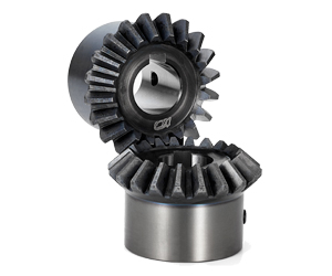
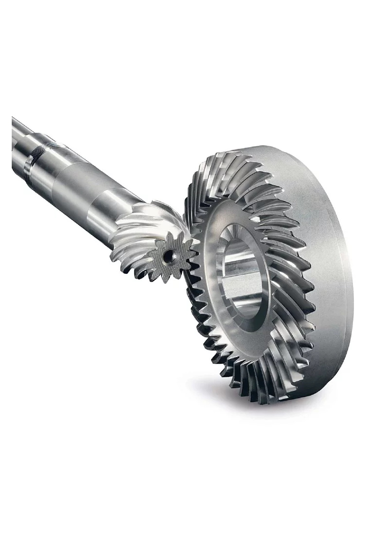
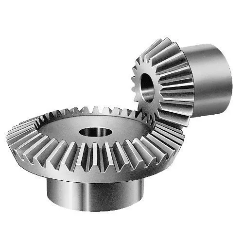
Gear shaft, Herringbone Gear Shaft, Bevel Gear, Eccentric Shaft mainly used on vessel engine, fan internal gear
1.1. Bevel Gear, Pinion Shaft Processing
Gear drawing— Simulation Modelling—Making casting model—Casting— Primary Detection—Rough machining—Hardening Tempering—Semi-finishing machining —Hobbing—Tooth Surface Quenching—Gear grinding—Gear Surface Carburzing—Inspection—Spray Anti-rust Oil—Package—Delivery
Gear Shaft drawing CHECK, Make Forging Mold, Forging Mold Quality Inspection Check, Machine Processing, Check Size\Hardness\Surface Finish and other technical parameters on drawing.
2.2. Bevel Gear Package
Spray anti-rust oil on Herringbone Gear Shaft, Wrap waterproof cloth around Gear Shaft for reducer, Prepare package by shaft shape&weight to choose steel frame, steel support or wooden box etc.
1.3. OEM Customized Pinion Shaft
We supply OEM SERVICE, customized herringbone gear shaft with big module, more than 1tons big weight, more than 3m length, 42CrMo/35CrMo or your specified required material gear shaft.
2.Product Technical info.
| Module | m | Range: 5~70 |
| Gear Teeth Number | z | OEM by drawing’s technical parameters |
| Teeth Height | H | OEM by drawing’s technical parameters |
| Teeth Thickness | S | OEM by drawing’s technical parameters |
| Tooth pitch | P | OEM by drawing’s technical parameters |
| Tooth addendum | Ha | OEM by drawing’s technical parameters |
| Tooth dedendum | Hf | OEM by drawing’s technical parameters |
| Working height | h’ | OEM by drawing’s technical parameters |
| Bottom clearance | C | OEM by drawing’s technical parameters |
| Pressure Angle | α | OEM by drawing’s technical parameters |
| Helix Angle, | OEM by drawing’s technical parameters | |
| Surface hardness | HRC | Range: HRC 50~HRC63(Quenching) |
| Hardness: | HB | Range: HB150~HB280; Hardening Tempering/ Hardened Tooth Surface |
| Surface finish | Range: Ra1.6~Ra3.2 | |
| Tooth surface roughness | Ra | Range: ≥0.4 |
| Gear Accuracy Grade | Grade Range: 5-6-7-8-9 (ISO 1328) | |
| Diameter | D | Range: 1m~16m |
| Weight | Kg | Range: Min. 100kg~Max. 80tons Single Piece |
| Gear Position | Internal/External Gear | |
| Toothed Portion Shape | Spur Gear/Bevel/Spiral/Helical/Straight | |
| Shaft shape | Herringbone Gear Shaft / Gear Shaft / Eccentric Shaft / Spur Gear / Girth Gear / Gear Wheel | |
| Material | Forging/ Casting |
Forging/ Casting 45/42CrMo/40Cr or OEM |
| Manufacturing Method | Cut Gear | |
| Gear Teeth Milling | √ | |
| Gear Teeth Grinding | √ | |
| Heat Treatment | Quenching /Carburizing | |
| Sand Blasting | Null | |
| Testing | UT\MT | |
| Trademark | TOTEM/OEM | |
| Application | Gearbox, Reducer, Petroleum,Cement,Mining,Metallurgy etc. Wind driven generator,vertical mill reducer,oil rig helical gear,petroleum slurry pump gear shaft |
|
| Transport Package | Export package (wooden box, steel frame etc.) | |
| Origin | China | |
| HS Code | 8483409000 |
Material Comparison List
| STEEL CODE GRADES COMPARISON | |||||
| CHINA/GB | ISO | ГΟСТ | ASTM | JIS | DIN |
| 45 | C45E4 | 45 | 1045 | S45C | CK45 |
| 40Cr | 41Cr4 | 40X | 5140 | SCr440 | 41Cr4 |
| 20CrMo | 18CrMo4 | 20ХМ | 4118 | SCM22 | 25CrMo4 |
| 42CrMo | 42CrMo4 | 38XM | 4140 | SCM440 | 42CrMo4 |
| 20CrMnTi | 18XГT | SMK22 | |||
| 20Cr2Ni4 | 20X2H4A | ||||
| 20CrNiMo | 20CrNiMo2 | 20XHM | 8720 | SNCM220 | 21NiCrMo2 |
| 40CrNiMoA | 40XH2MA/ 40XHMA |
4340 | SNCM439 | 40NiCrMo6/ 36NiCrMo4 |
|
| 20CrNi2Mo | 20NiCrMo7 | 20XH2MA | 4320 | SNCM420 | |
3.Totem Service
TOTEM Machinery focus on supplying GEAR SHAFT, ECCENTRIC SHAFT, HERRINGBONE GEAR, BEVEL GEAR, INTERNAL GEAR and other parts for transmission devices & equipments(large industrial reducers & drivers). Which were mainly used in the fields of port facilities, cement, mining, metallurgical industry etc. We invested in several machine processing factories,forging factories and casting factories,relies on these strong reliable and high-quality supplier network, to let our customers worry free.
TOTEM Philosophy: Quality-No.1, Integrity- No.1, Service- No.1
24hrs Salesman on-line, guarantee quick and positive feedback. Experienced and Professional Forwarder Guarantee Log. transportation.
4.About TOTEM
1. Workshop & Processing Strength
2. Testing Facilities
3. Customer Inspection & Shipping
5. Contact Us
ZheJiang CHINAMFG Machinery Co.,Ltd
Facebook: ZheJiang Totem
| Application: | Motor, Motorcycle, Machinery, Marine, Cement |
|---|---|
| Hardness: | Hardened Tooth Surface |
| Gear Position: | Internal/External |
| Manufacturing Method: | Cast Gear |
| Toothed Portion Shape: | Bevel Wheel |
| Material: | Cast Steel |
| Customization: |
Available
| Customized Request |
|---|
What are the factors to consider when selecting miter gears for an application?
When selecting miter gears for an application, several factors need to be taken into consideration to ensure optimal performance and compatibility. Here are some key factors to consider:
1. Load Requirements:
Determine the magnitude and type of load that the miter gears will be subjected to. Consider factors such as torque, speed, and direction of rotation. This information helps in selecting miter gears with the appropriate load capacity and tooth strength to handle the application’s requirements.
2. Gear Ratio:
Identify the desired gear ratio, which is the ratio of the number of teeth between the input and output gears. The gear ratio determines the speed and torque relationship between the gears. Select miter gears with a gear ratio that meets the specific speed and torque requirements of the application.
3. Accuracy and Precision:
Determine the required level of accuracy and precision for the application. Certain applications, such as precision instruments or robotics, may require miter gears with high precision and low backlash to ensure accurate motion transmission.
4. Space Constraints:
Evaluate the available space for the miter gears within the system. Consider the gear dimensions, shaft orientations, and clearance requirements. Choose miter gears that can fit within the available space while still allowing for proper meshing and alignment.
5. Noise and Vibration:
Consider the acceptable levels of noise and vibration for the application. Spiral bevel gears, for example, are known to reduce noise and vibration compared to straight bevel gears. Select miter gears with suitable tooth profiles and designs to minimize noise and vibration if required.
6. Lubrication and Maintenance:
Assess the lubrication and maintenance requirements of the miter gears. Some miter gears may require specific lubrication methods or periodic maintenance. Consider the ease of access for lubrication and maintenance tasks when selecting miter gears.
7. Environmental Factors:
Take into account the environmental conditions in which the miter gears will operate. Factors such as temperature extremes, moisture, dust, chemicals, or exposure to corrosive substances can impact gear performance. Choose miter gears that are suitable for the specific environmental conditions of the application.
8. Cost and Availability:
Consider the cost and availability of the miter gears. Evaluate the overall value proposition, including the initial cost, long-term maintenance costs, and the availability of spare parts. Balance the cost factor with the desired performance and reliability.
By considering these factors, engineers and designers can select miter gears that are well-suited for the application’s requirements, ensuring efficient and reliable operation.
“`
What is the role of the pitch angle in miter gear design?
In miter gear design, the pitch angle plays a significant role in determining the characteristics and performance of the gears. Here’s an explanation of its role:
1. Definition of Pitch Angle:
The pitch angle in miter gear design refers to the angle between the gear’s tooth face and a plane perpendicular to the gear’s axis. It is typically denoted by the Greek letter “β” (beta). The pitch angle determines the shape and orientation of the gear teeth.
2. Tooth Profile:
The pitch angle influences the tooth profile of miter gears. By altering the pitch angle, the shape, size, and thickness of the gear teeth can be adjusted. Different pitch angles result in variations in the tooth geometry, such as tooth thickness, tooth height, and the angle of the tooth face.
3. Contact Ratio:
The pitch angle affects the contact ratio between the gear teeth. The contact ratio refers to the number of teeth in contact at any given moment during the rotation of the gears. An appropriate pitch angle helps optimize the contact ratio, ensuring sufficient tooth engagement and load distribution across the gear surfaces. This contributes to smoother operation, reduced noise, and improved gear life.
4. Strength and Load Distribution:
The pitch angle influences the strength and load distribution capabilities of miter gears. A proper pitch angle ensures optimal load transmission across the gear teeth, preventing concentrated stresses and reducing the risk of tooth failure or breakage. By selecting the appropriate pitch angle, designers can achieve the desired strength and load-carrying capacity for the specific application.
5. Gear Efficiency:
The pitch angle also affects the efficiency of miter gears. By considering factors such as tooth contact, sliding friction, and tooth deflection, the pitch angle can be optimized to minimize energy losses during gear meshing. Efficient gear design with an appropriate pitch angle contributes to higher overall system efficiency and reduced power consumption.
6. Noise and Vibration:
The pitch angle plays a role in determining the noise and vibration characteristics of miter gears. Improper pitch angles can result in undesirable effects, such as excessive noise, vibration, and tooth impact. By carefully selecting the pitch angle, gear designers can minimize these effects, leading to quieter operation and improved gear performance.
7. Meshing Compatibility:
When using miter gears in pairs, the pitch angles of both gears should be compatible to ensure proper meshing and smooth operation. The pitch angles need to be designed and manufactured with precision to ensure accurate alignment and optimal tooth engagement.
In summary, the pitch angle in miter gear design influences the tooth profile, contact ratio, strength and load distribution, gear efficiency, noise and vibration characteristics, and meshing compatibility. By selecting an appropriate pitch angle, gear designers can achieve the desired performance, durability, and efficiency for specific applications.
Can you explain the unique design of miter gear teeth?
The design of miter gear teeth is distinct and plays a crucial role in the functionality of these gears. Here’s a detailed explanation:
1. Tooth Shape:
Miter gear teeth have a straight shape, similar to spur gears. However, unlike spur gears where the teeth are parallel to the gear axis, miter gear teeth are cut at a right angle to the gear’s face. This allows the teeth to engage correctly when two miter gears mesh together at a 90-degree angle.
2. Equal Number of Teeth:
Miter gears have an equal number of teeth on both gears in a pair. This ensures proper meshing and smooth transmission of rotational motion between the gears. The equal number of teeth is essential for maintaining a constant speed ratio and preventing any slippage or irregular motion.
3. Conical Shape:
Another unique aspect of miter gear teeth is the conical shape of the gears themselves. The teeth are cut on the conical surface, which allows for proper engagement and transmission of motion between intersecting shafts. The conical shape ensures that the teeth mesh correctly, providing efficient power transmission at the desired angle.
4. Meshing at 90-Degree Angle:
Miter gears are designed to mesh at a 90-degree angle, allowing for power transmission between intersecting shafts. The teeth are specifically cut to facilitate this arrangement, ensuring that the gears engage smoothly and transmit rotational motion without any loss or disruption.
5. Tooth Contact and Load Distribution:
When miter gears mesh, the contact between the teeth occurs along a single line, known as the line of contact. This concentrated contact area enables effective load distribution and ensures that the gear teeth bear the transmitted torque evenly. Proper tooth contact is vital for minimizing wear and maintaining the longevity of the gears.
6. Lubrication and Noise Reduction:
The unique design of miter gear teeth can influence lubrication and noise levels. Adequate lubrication is essential to reduce friction and wear between the teeth during operation. Additionally, the straight tooth profile of miter gears tends to produce more noise compared to gears with helical or curved teeth. Proper lubrication and noise reduction measures are often employed to optimize the performance of miter gears.
In summary, the unique design of miter gear teeth includes their straight shape, equal number of teeth, conical shape of the gears, meshing at a 90-degree angle, tooth contact along a line, and considerations for lubrication and noise reduction. These design features ensure efficient power transmission, proper load distribution, and reliable operation in mechanical systems that utilize miter gears.


editor by CX 2023-12-13