Product Description
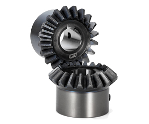
Forged Bevel Gear 90 Degree Best Quanlity Miter Spiral Supplyer Forged Plastic Sintered Metal Stainless Steel CHINAMFG for Test Machine Curtain Forged Bevel Gear
Application of Forged Bevel Gear
Forged bevel gears are used in a wide variety of applications where high strength, durability, and efficiency are required. Some common applications include:
- Machine tools: Forged bevel gears are used in machine tools to transmit power between the spindle and the workpiece.
- Wind turbines: Forged bevel gears are used in wind turbines to transmit power from the rotor to the generator.
- Robotics: Forged bevel gears are used in robotics to transmit power from the motor to the actuator.
- Automotive: Forged bevel gears are used in automotive applications such as differentials and transfer cases.
- Aerospace: Forged bevel gears are used in aerospace applications such as jet engines and helicopters.
Forged bevel gears offer a number of advantages over other types of gears, including:
- High strength: Forged bevel gears are very strong and can withstand high loads.
- Durability: Forged bevel gears are very durable and can withstand a high number of cycles.
- Efficiency: Forged bevel gears are very efficient and can transmit power with minimal losses.
- Dimensional accuracy: Forged bevel gears are very dimensionally accurate, which is important for applications where precision is required.
- Low cost: Forged bevel gears are relatively low in cost, making them a cost-effective option for many applications.
Forged bevel gears are a versatile and reliable type of gear. They are available in a wide range of sizes and materials to meet the needs of different applications.
Here are some of the specific advantages of using forged bevel gears in differentials:
- Increased strength: Forged bevel gears are stronger than cast bevel gears, which makes them more resistant to fatigue and wear.
- Improved durability: Forged bevel gears are more durable than cast bevel gears, which means they can withstand more abuse and last longer.
- Enhanced efficiency: Forged bevel gears are more efficient than cast bevel gears, which means they can transmit power with less loss.
- Reduced noise: Forged bevel gears are quieter than cast bevel gears, which makes them ideal for use in vehicles and other applications where noise is a concern.
Overall, forged bevel gears offer a number of advantages over cast bevel gears, making them a better choice for many applications.
| Application: | Motor, Electric Cars, Motorcycle, Machinery, Marine, Toy, Agricultural Machinery, Car |
|---|---|
| Hardness: | Hardened Tooth Surface |
| Gear Position: | Internal Gear |
| Manufacturing Method: | Cast Gear |
| Toothed Portion Shape: | Worm Gear |
| Material: | Stainless Steel |
| Samples: |
US$ 9999/Piece
1 Piece(Min.Order) | |
|---|
What are the factors to consider when selecting miter gears for an application?
When selecting miter gears for an application, several factors need to be taken into consideration to ensure optimal performance and compatibility. Here are some key factors to consider:
1. Load Requirements:
Determine the magnitude and type of load that the miter gears will be subjected to. Consider factors such as torque, speed, and direction of rotation. This information helps in selecting miter gears with the appropriate load capacity and tooth strength to handle the application’s requirements.
2. Gear Ratio:
Identify the desired gear ratio, which is the ratio of the number of teeth between the input and output gears. The gear ratio determines the speed and torque relationship between the gears. Select miter gears with a gear ratio that meets the specific speed and torque requirements of the application.
3. Accuracy and Precision:
Determine the required level of accuracy and precision for the application. Certain applications, such as precision instruments or robotics, may require miter gears with high precision and low backlash to ensure accurate motion transmission.
4. Space Constraints:
Evaluate the available space for the miter gears within the system. Consider the gear dimensions, shaft orientations, and clearance requirements. Choose miter gears that can fit within the available space while still allowing for proper meshing and alignment.
5. Noise and Vibration:
Consider the acceptable levels of noise and vibration for the application. Spiral bevel gears, for example, are known to reduce noise and vibration compared to straight bevel gears. Select miter gears with suitable tooth profiles and designs to minimize noise and vibration if required.
6. Lubrication and Maintenance:
Assess the lubrication and maintenance requirements of the miter gears. Some miter gears may require specific lubrication methods or periodic maintenance. Consider the ease of access for lubrication and maintenance tasks when selecting miter gears.
7. Environmental Factors:
Take into account the environmental conditions in which the miter gears will operate. Factors such as temperature extremes, moisture, dust, chemicals, or exposure to corrosive substances can impact gear performance. Choose miter gears that are suitable for the specific environmental conditions of the application.
8. Cost and Availability:
Consider the cost and availability of the miter gears. Evaluate the overall value proposition, including the initial cost, long-term maintenance costs, and the availability of spare parts. Balance the cost factor with the desired performance and reliability.
By considering these factors, engineers and designers can select miter gears that are well-suited for the application’s requirements, ensuring efficient and reliable operation.
“`
How do you calculate the gear ratio in a miter gear assembly?
The gear ratio in a miter gear assembly can be calculated by considering the number of teeth on the gears involved. Here’s a step-by-step explanation:
1. Determine the Number of Teeth:
Identify the number of teeth on both the driving gear (input gear) and the driven gear (output gear) in the miter gear assembly. The number of teeth can usually be found in the gear specifications or by physically counting the teeth.
2. Calculate the Gear Ratio:
To calculate the gear ratio, divide the number of teeth on the driven gear (output gear) by the number of teeth on the driving gear (input gear). The formula for calculating the gear ratio is:
Gear Ratio = Number of Teeth on Driven Gear / Number of Teeth on Driving Gear
3. Simplify the Ratio (Optional):
If the resulting gear ratio is a fraction, it can be simplified to its simplest form. Divide both the numerator and the denominator by their greatest common divisor to simplify the ratio.
4. Interpret the Gear Ratio:
The gear ratio indicates the relationship between the rotational speed or angular velocity of the driving gear and the driven gear. It represents how many times the driven gear rotates for each rotation of the driving gear. For example, a gear ratio of 2:1 means that the driven gear rotates twice for every rotation of the driving gear.
5. Consider the Significance:
The gear ratio has practical implications in determining the mechanical advantage and speed reduction/amplification in a miter gear assembly. A gear ratio greater than 1 indicates a speed reduction and increased torque, while a gear ratio less than 1 indicates a speed amplification and decreased torque.
In summary, the gear ratio in a miter gear assembly is calculated by dividing the number of teeth on the driven gear by the number of teeth on the driving gear. This ratio represents the relationship between the rotational speeds of the gears and provides insights into the mechanical advantage and speed transformation in the gear assembly.
What are miter gears and how are they used?
Miter gears are a type of bevel gears that have equal numbers of teeth and are used to transmit motion and power between intersecting shafts. Here’s a detailed explanation:
1. Gear Design:
Miter gears have a conical shape with teeth cut at an angle of 90 degrees to the gear’s face. The teeth are cut in a straight manner, similar to spur gears, but instead of being parallel to the gear’s axis, they are cut at a right angle to transmit motion between intersecting shafts.
2. Intersecting Shafts:
Miter gears are primarily used to transmit power and motion between two shafts that intersect at a 90-degree angle. The gear’s conical shape allows the teeth to mesh correctly when the shafts are perpendicular to each other.
3. Change of Shaft Direction:
Miter gears are commonly used to change the direction of rotation between intersecting shafts. By meshing the teeth of two miter gears, the input shaft’s rotational motion can be transferred to the output shaft at a 90-degree angle, effectively changing the direction of rotation.
4. Speed Reduction or Increase:
Depending on the arrangement of the miter gears, they can be used to achieve speed reduction or speed increase. By using different numbers of teeth on the miter gears or combining them with other gears, such as spur gears, the rotational speed can be adjusted to match the desired output speed.
5. Compact Design:
Miter gears are known for their compact design, making them suitable for applications where space is limited. The intersecting shafts and the conical shape of the gears allow for efficient power transmission while occupying a small footprint.
6. Applications:
Miter gears find applications in various industries and devices, including:
- Power transmission systems
- Automotive differentials
- Mechanical clocks
- Robotics
- Printing machinery
- Woodworking tools
- Camera lenses
In summary, miter gears are bevel gears with equal numbers of teeth that are used to transmit motion and power between intersecting shafts at a 90-degree angle. They are commonly employed to change the direction of rotation, achieve speed reduction or increase, and maintain a compact design in various mechanical systems.


editor by CX 2023-09-25